Reflow Oven Controller
Feb 2026 · Team of 6, ELEC 291 Project 1 · Shipped
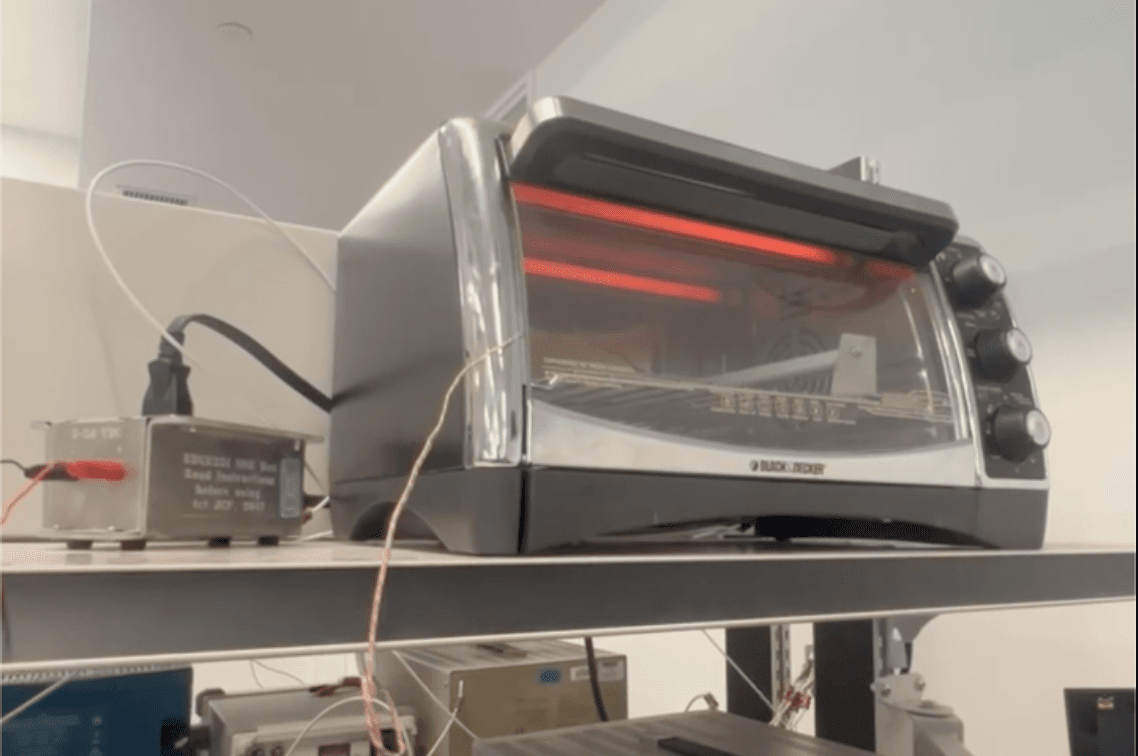
An SMD reflow oven controller built on a CV-8052 microcontroller and a retrofitted toaster oven. The firmware is written entirely in 8051 assembly and runs a 6-state FSM (idle → preheat → soak → ramp → reflow → cool) that drives a solid-state relay to follow a user-configured solder profile.
Temperature is measured with a K-type thermocouple front-end built around an OP07 op-amp and an LM335 cold-junction reference, sampled by the DE10-Lite's on-chip ADC. The system held ±3 °C accuracy across 25 to 240 °C and reflowed test boards during the project demonstration. A Python dashboard pulls UART telemetry at 115200 baud, draws a live strip-chart against the predicted profile, and exports an Excel report when the cycle completes.
Specs
- Microcontroller
- CV-8052 on the DE10-Lite (8051-class soft processor)
- Accuracy
- ±3 °C over 25 to 240 °C
- Control loop
- Hybrid: 100 % drive during ramps, low-frequency time-proportioning during soak / dwell
- FSM
- Idle → Preheat → Soak → Ramp-to-reflow → Reflow → Cooldown
- Sensor front-end
- K-type thermocouple → OP07 difference amplifier → ADC; LM335 cold-junction reference on a second ADC channel
- Power switching
- FQU13N06LS MOSFET driving an SSR; oven rated 1500 W
- Telemetry
- UART @ 115200 baud → Python live strip-chart + auto-generated .xlsx report
- Safety
- 60 s thermal-rise watchdog, parameter-bound enforcement, audible error tones
- Build effort
- ~220 hours across the team
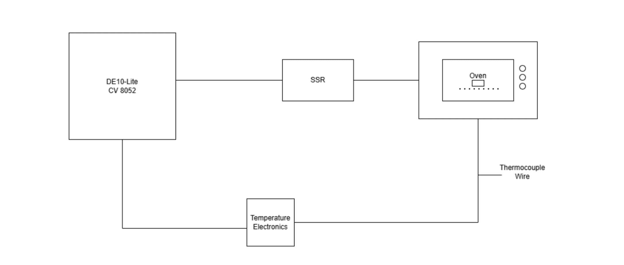
System overview
Hardware
Two ADC channels on the DE10-Lite acquire temperature-related voltages: channel 0 reads the LM335 cold-junction reference (10 mV/K, calibrated against a digital multimeter), and channel 1 reads the OP07 op-amp output that amplifies the K-type thermocouple's millivolt-level signal up into the ADC's 12-bit input range.
The op-amp gain network uses precision-matched resistors and an LMC7660 charge-pump inverter to provide a controlled negative rail. We chose the OP07 specifically for its low offset voltage; observed gain still varied between physical chips, so we screened parts and kept the best-behaved one. SSR control runs through a single GPIO that drives the gate of an FQU13N06LS N-channel MOSFET, which closes the SSR's input loop and switches the oven's mains supply.
User input goes through a 4×4 matrix keypad and dedicated start/stop tactile buttons; output goes to a 16×2 LCD (current state, temperatures, set parameters), a 7-segment display (large oven-temperature readout), and a piezo speaker (state-change beeps and error tones). All UI updates are scheduled by the same 1 ms timer that drives the control loop, so display refresh never blocks the FSM.
Firmware
The firmware is written entirely in 8051 assembly and follows a non-blocking, interrupt-driven structure. Timer 0 generates the 1 ms system tick: every 250 ticks (250 ms) it sets a quarter-second flag consumed by the main loop for ADC sampling, display refresh, and serial transmission; every 1000 ticks it advances the second / minute counters used by the FSM.
The reflow process runs as a 6-state FSM. State transitions are driven by either temperature thresholds (e.g., "current ≥ soak setpoint") or elapsed-time counters. The SSR is gated by a powerPercent macro that converts a desired duty cycle (%) and a window length (s) into an on-time. During ramps the macro is bypassed and the SSR runs at 100 %; during soak and dwell it produces low-frequency PWM well-matched to the oven's thermal mass.
Timer 0 is shared with the speaker: when a tone is being played, the same timer reload value is swapped to the desired note's period and toggles the SOUND_OUT pin in the ISR. This freed up Timer 2 to be dedicated to UART baud-rate generation, which the assignment required at 115200 baud.
powerPercent MAC
    mov x+0, %0
    mov x+1, #0
    mov x+2, #0
    mov x+3, #0
    Load_Y_Var16(%1)
    lcall mul32

    load_y(100)
    lcall div32

    mov %2+0, x+0
    mov %2+1, x+1
ENDMAC
powerPercent macro: converts a duty-cycle % into a window on-time for the SSRValidation & telemetry
A Python dashboard reads UART frames at 115200 baud and renders a live temperature strip-chart against a predicted profile generated from the user-entered soak / reflow parameters. When the firmware emits a DONE token at the end of cooldown, the dashboard saves a snapshot PNG and exports an .xlsx report with the recorded data and an embedded comparison chart.
Temperature accuracy was validated end-to-end against a calibrated digital multimeter from room temperature up to 240 °C across multiple back-to-back heating cycles. The system passed the laboratory's temperature-validation program with margin to spare.
Two extension modes were also implemented: a microwave-style timed-cook mode with eight food presets, and a "magic keyboard" mode mapping the keypad to a two-octave musical scale, sharing the same speaker and SSR safety logic.
Challenges & decisions
- Op-amp gain network was sensitive to component tolerances even with matched resistors; characterizing several physical OP07s and selecting the best-behaved one was faster than tightening the BOM.
- Sharing Timer 0 between the system tick and the speaker required careful ISR mode switching. Early revisions accidentally re-entered the audio path during the timer tick and lost real-time accuracy.
- Interrupts had to be temporarily disabled around any call into the integer math library; missing this caused intermittent ADC corruption that took several hours to track down.