Field-Following Autonomous Robot
Apr 2026 · Team of 6, ELEC 291 Project 2 · Shipped
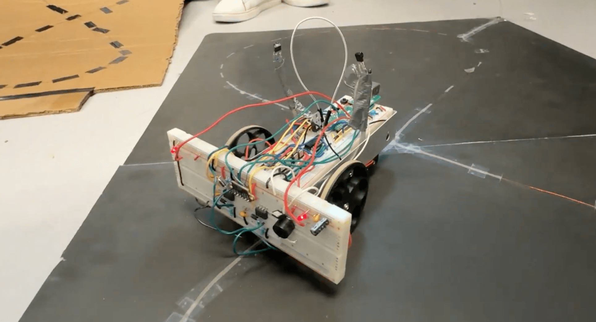
An autonomous robot that tracks a current-carrying guide wire using three LC-tank pickup inductors and an adaptive baseline detector, executes a pre-programmed sequence of turns at intersections, and falls back to manual control via a 38 kHz infrared remote. The robot ran through three different paths on a figure-8 demonstration track and stopped autonomously when an obstacle entered the VL53L0X Time-of-Flight sensor's view.
Control is split across two microcontrollers from different families: an STM32L051 (ARM Cortex-M0+) on the robot, and an EFM8LB12F64 (8051 family) on the remote. Both are programmed in C. Motor power is delivered through a discrete N+P MOSFET H-bridge isolated from the logic supply by an LTV-847 quad optocoupler, which kept motor switching noise out of the inductive sensors.
Specs
- Robot MCU
- STM32L051 (ARM Cortex-M0+)
- Remote MCU
- EFM8LB12F64 (8051 family)
- Field-detection front-end
- Three LC tanks @ ~16.876 kHz, LM358 op-amps, k = 160
- Sensor placement
- Two collinear (left / right) + one orthogonal (intersection)
- Motor driver
- Discrete N+P MOSFET H-bridge with LTV-847 optocoupler isolation
- PWM
- Software PWM, 100 Hz effective, 1000-count frame, +25 % left-motor trim
- IR link
- 38 kHz modulated, time-encoded commands, two TSOP33338 receivers OR'd at the robot
- Collision sensor
- VL53L0X Time-of-Flight over I²C, 200 mm stop threshold
- Build effort
- ~240 hours across the team
System overview
Hardware
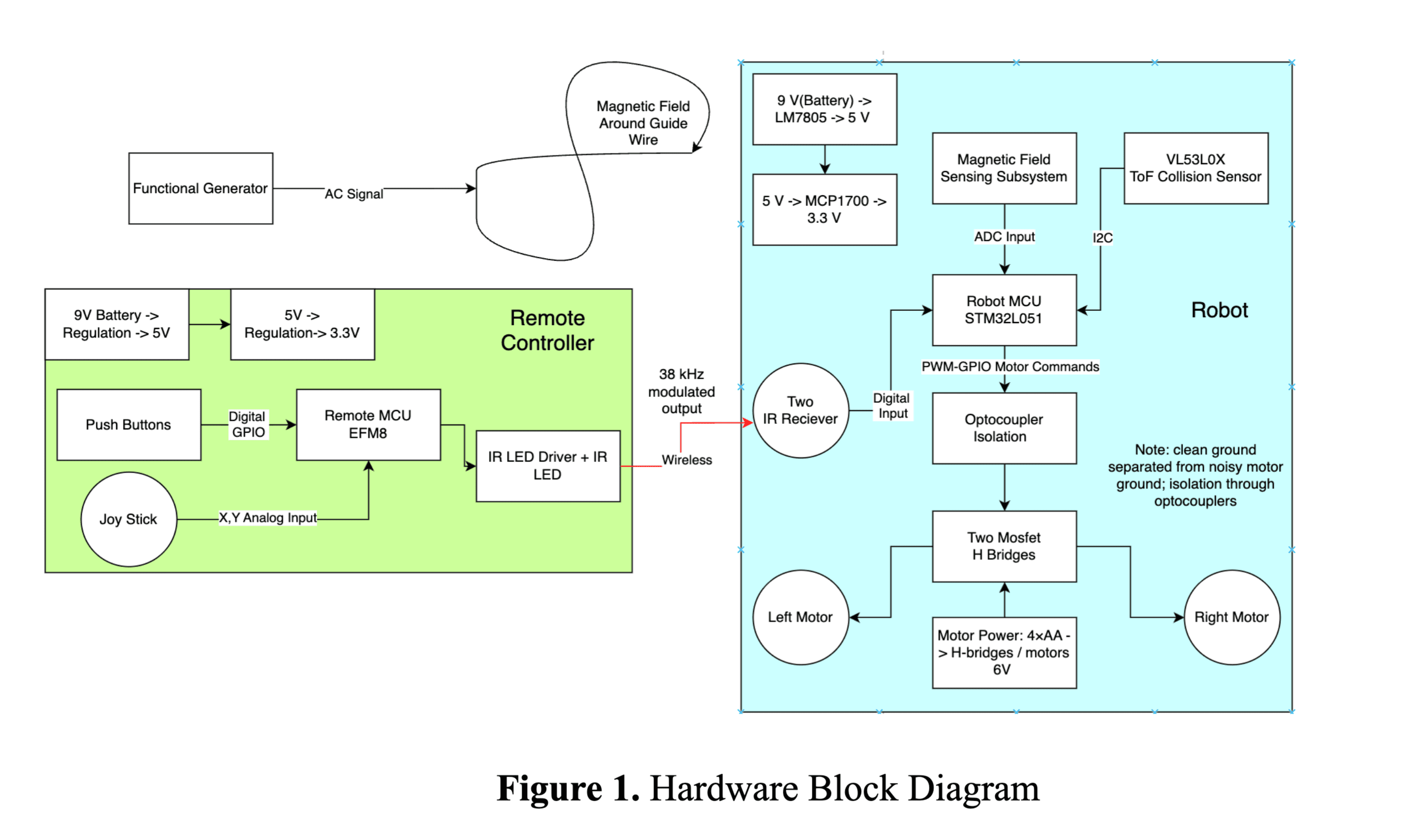
Power on the robot is regulated in two stages: a 9 V battery feeds an LM7805 to produce 5 V, which then feeds an MCP1700 to produce the 3.3 V logic rail. A separate 4×AA pack (6 V) powers the H-bridges and motors so motor switching transients can't pull the logic rail. Grounds are split into a "clean" ground for the MCU and ADC and a "noisy" ground for the H-bridge; the two are joined at a single star point.
Three LC tanks tuned to ~16.876 kHz pick up the field generated around the guide wire. Each tank's voltage is amplified through an LM358 op-amp stage and rectified before reaching the STM32's ADC. Two of the inductors are mounted collinearly at the front of the robot to feed left/right steering; the third is rotated 90° and reads only when the robot crosses a perpendicular wire, which triggers an intersection event.
Each motor has its own H-bridge made from four MOSFETs (two N-channel, two P-channel). The LTV-847 quad optocoupler sits between the STM32's GPIO and each H-bridge driver pin, completely isolating logic from the motor supply. One of the two motors consistently ran slightly weaker than the other under the same drive (likely a manufacturing tolerance), so the firmware applies a +25 % trim to the left-motor command to keep the robot driving straight.
Firmware
The robot firmware is split into modules for initialization, motor control, magnetic-field sensing, autonomous navigation, manual IR control, and collision safety. Although the runtime is a single cooperative loop, modules communicate through shared structures so each piece could be developed and tested independently.
Motor control is implemented as software PWM on a 100 kHz Timer 2 ISR. Four GPIO outputs (two per H-bridge) are gated by per-channel compare values; the ISR increments a shared counter and updates the four pins each tick. The PWM frame contains 1000 counts, giving an effective 100 Hz drive frequency, well below the motor inductance corner but fast enough that the chassis behaves continuously.
Field sensing uses an adaptive-baseline filter: each ADC channel is averaged over four conversions, then a slow running-average baseline is updated only when the detector is currently considered inactive. The instantaneous "signal" is the absolute difference between the filtered reading and the baseline, with separate entry / exit hysteresis bands so the detector latches cleanly. This survives drift in the analog front end without losing responsiveness when the wire actually appears.
The autonomous navigator is a small FSM (follow / intersection / lost / stop). In follow mode, the controller compares the left and right detector signals and slows the inside wheel if the difference exceeds the steering deadband. When the orthogonal intersection sensor triggers, the firmware looks up the next action (straight / left / right / stop) from the active path table, stops, beeps, executes the turn for a fixed time, and re-enters follow mode.
case ROBOT_AUTO_FOLLOW:
    if (intersection_started(context, detected_now)) {
        g_active_action = path_context_on_intersection(context);
        motor_stop();
        speaker_beep(1000, 200);
        delayms(400);
        if (g_active_action == PATH_LEFT || g_active_action == PATH_RIGHT) {
            run_path_action(g_active_action);
            delayms(900);
            motor_stop();
            g_state = ROBOT_AUTO_FOLLOW;
        } else if (g_active_action == PATH_STOP) {
            g_state = ROBOT_AUTO_STOP;
        }
        break;
    }
    run_follow_controller(sensors);
break;Remote control
The remote sits on an EFM8LB12F64 and reads two analog joystick axes through the on-chip 14-bit ADC plus six tactile buttons. Timer 0 toggles a GPIO at 38 kHz to modulate the IR LED, and a single byte-length-encoded command is sent in 50 ms windows: button presses send fixed-length pulses, and joystick deflections scale linearly into the pulse length using V_button = 25 + 10·V_x for X and V_button = 70 + 10·V_y for Y.
On the robot side, two TSOP33338 receivers are placed on small antennas and wired into an OR gate so that the receiver coverage area is roughly the union of the two. A pulse-width discriminator on the STM32 maps received pulse lengths back to commands: 2 to 8 ms for joystick X, 8 to 18 ms for joystick Y, then dedicated bands for honk, mode toggle, path swap, pause, speed down, and speed up. Joystick X/Y are mixed into per-wheel commands as left = y + x, right = y − x.
Validation
All three pre-configured paths were run on the figure-8 guide-wire layout and consistently completed their turn sequences. Intersection detection was reliable at the tuned base speed of 600 (out of 1000); above that the chassis sometimes passed over an intersection too quickly to register, and below ~400 the steering felt sluggish. Adjustable speed via the remote let us tune this live during the demonstration.
We also characterized the IR link by sending 10 commands at increasing horizontal distances, with the remote held at receiver height. All commands landed within 2 m; success rate dropped roughly linearly to 0 % at 3.8 m. IR pollution from neighbouring groups was the main failure mode.
Challenges & decisions
- Motor switching noise initially coupled into the inductive sensors badly enough to corrupt the steering signal. Adding the LTV-847 optocoupler stage between the STM32 GPIOs and the H-bridge gates and splitting the grounds dropped the noise to a manageable level.
- The left motor consistently ran weaker than the right under identical drive, almost certainly a manufacturing tolerance. The firmware applies a +25 % trim to the left command instead of swapping motors, which gave straighter long-line tracking than mechanical alignment did.
- Tuning the base forward speed against intersection detection required an adjustable-speed feature on the remote: too fast meant missed intersections, too slow felt sluggish. Locking the demo at ~600 / 1000 hit the right balance.