Capacitance Meters (Dual Platform)
Oct to Nov 2025 · Solo, ELEC 291 Module 4 · Coursework
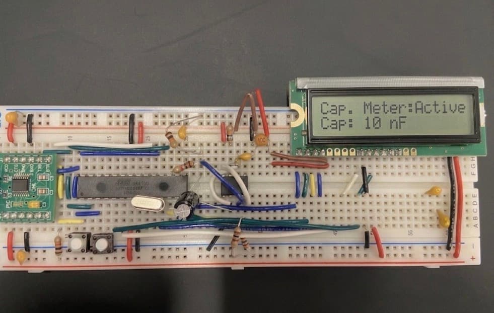
Two capacitance meters built on different microcontroller families: an EFM8 and an STM32. The principle is the same on both: a 555-timer astable oscillates at a frequency that depends on the capacitor under test, the MCU counts pulses on a hardware timer input, and software reverses the 555 frequency formula to recover capacitance.
As an extension I also designed a 555 equivalent from discrete blocks (two LM393 comparators with the standard 1/3 V_CC and 2/3 V_CC voltage dividers, an SR latch built from NAND gates, and a 2N3904 transistor for the discharge path), and ran the same firmware against it to compare against the IC. Operating range: 1 nF to 1 µF.
Specs
- MCUs
- EFM8LB12F64 (8051 family) and STM32 (ARM Cortex)
- EFM8 system clock
- 72 MHz internal oscillator
- Astable target
- f = 1.44 / ((R_A + 2·R_B)·C) with R_A = R_B = 10 kΩ
- Range
- 1 nF to 1 µF (rejected outside this band)
- Frequency capture
- Timer 0 input on P0.0 (EFM8); pulse counting in software
- Stability filter
- Δf < 5 Hz across 3 consecutive samples = stable; > 5 % rel. change = noisy
- LCD modes
- 4 modes: instantaneous / min-max / running average / angular freq
- Discrete 555
- 2× LM393 comparators, NAND-gate SR latch, 2N3904 discharge
Discrete 555 equivalent
The 555 internally is a pair of comparators whose thresholds are set by a 5 kΩ / 5 kΩ / 5 kΩ divider (giving 1/3 V_CC and 2/3 V_CC), an SR flip-flop, and a transistor that pulls the timing capacitor to ground when the latch is in the discharge state. I rebuilt that from parts in the kit: two channels of an LM393 dual comparator (open-collector, needed pull-ups), an SR latch from NAND gates, and a 2N3904 driven from the latch's Q output. Base resistor sized for β = 50 worst-case at 50 mA collector current.
Once the discrete circuit was oscillating at 2.88 kHz with R_A = R_B = 4.7 kΩ and C = 0.1 µF (matching the textbook 555 formula), I drew the schematic and the comparator-input / Q-output waveforms. The discrete version runs noticeably noisier than the IC near the threshold crossings (the open-collector outputs ringing into the divider), but it tracks the formula well across the full capacitance range.
Firmware
The EFM8 firmware uses Timer 0 in counter mode with the input wired to P0.0. The 555's output drives that pin, so each oscillator cycle increments the timer; sampling the count over a fixed 1 s window gives frequency directly. Capacitance falls out of the rearranged formula C = 1.44 / ((R_A + 2·R_B)·f), with R_A = R_B = 10 kΩ baked in as a constant.
There's a small stability filter on top: a reading is considered stable when three consecutive samples differ by less than 5 Hz; relative changes greater than 5 % flip a 'noisy' flag for the LCD. The user can cycle through 4 display modes with a button on P2.1: instantaneous reading, observed min/max, running average over the session, and the equivalent angular frequency.
Porting to the STM32 was mostly a matter of swapping the timer / GPIO peripheral configuration; the math and the user interface ported directly. The STM32 build feels snappier mostly because the LCD redraws are fast enough to make the readings look continuous.
#define SYSCLK 72000000L
#define BAUDRATE 115200L

// Resistor values used in 555 circuit
#define R_A 10000.0   // 10k
#define R_B 10000.0   // 10k
#define K_555 (1.44 / (R_A + 2.0 * R_B))

// Valid capacitance range
#define C_MIN 1e-9f   // 1 nF
#define C_MAX 1e-6f   // 1 uF

// Stability / signal quality
#define STABLE_DELTA_HZ 5      // Hz threshold for stable reading
#define STABLE_SAMPLES 3       // consecutive stable samples needed
#define NOISY_REL_THRESH 0.05f // 5% relative change considered noisy