Battery Temperature Monitor PCB
Dec 2025 · Solo · Personal project
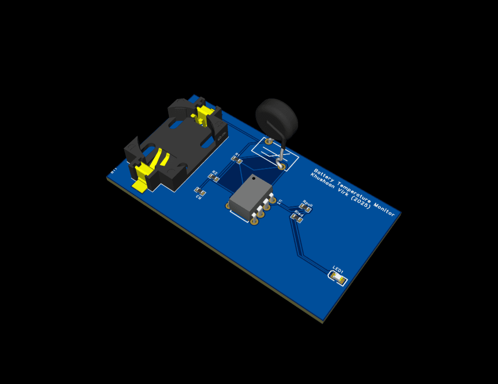
A small battery-powered analog over-temperature alert circuit, built to get familiar with PCB design software. An NTC5D-9 thermistor sits in a resistor divider against a fixed reference; an LM393 comparator switches its open-collector output and lights a yellow 0805 SMD LED once the divider voltage crosses the reference.
Designed entirely in KiCad: schematic capture, 2-layer board layout with a continuous ground pour, manual analog trace routing, DRC verification, and Gerber export. The whole thing runs from a single CR2032 coin cell.
Specs
- Power
- CR2032 coin cell (3 V)
- Sensor
- NTC5D-9 in 10 kΩ / 10 kΩ divider
- Reference
- 10 kΩ / 10 kΩ resistor divider on the same supply (rail-ratiometric)
- Comparator
- LM393P3 with 10 kΩ pull-up on the open-collector output
- Indicator
- KT-0805Y SMD LED, 330 Ω current limit
- Board
- 2-layer with continuous ground pour, mixed THT + SMD, manual routing
- Tools
- KiCad: schematic, layout, 3D render, Gerbers
System overview
Circuit
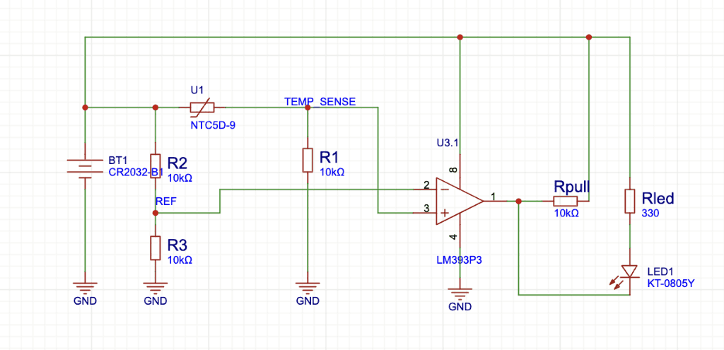
Two 10 kΩ legs sit either side of the NTC: R1 makes a divider with the thermistor that produces TEMP_SENSE, and R2/R3 make a fixed reference (REF). Because both dividers share the same supply, the trip point stays ratiometric. Battery voltage drift cancels out as long as the cell can still drive the LM393's input bias. NTC resistance falls with temperature, so TEMP_SENSE rises with temperature; once TEMP_SENSE crosses REF, the LM393's open-collector output pulls low and the LED lights through Rled.
The LM393 was chosen over an op-amp Schmitt-trigger setup because the open-collector output makes the LED drive trivial (just a pull-up + current-limit resistor), the part runs comfortably from 3 V coin-cell territory, and a single device gives me two channels per package if I want to add a second threshold later. There's no hysteresis on this rev. At the trip point the output can chatter, which is the obvious thing to revisit on rev 2.
Layout
The board is 2-layer with a continuous top-side ground pour and short, manually routed analog traces between the divider, the LM393 inputs, and the comparator output. Component placement keeps the NTC, the divider resistors, and the comparator inputs physically clustered so the high-impedance sense path stays short. Long analog traces on a high-impedance node pick up noise easily, and at coin-cell currents there's no margin to filter it out aggressively.
The CR2032 holder is dropped on the left, the LM393 in the center, and the indicator LED sits at the far right edge so the board can be mounted with the LED facing out. DRC ran clean on a standard 2-layer ruleset and the Gerbers are ready for fab.