AC Phasor Voltmeter
Feb 2026 · Solo, ELEC 291 Lab 5 · Coursework
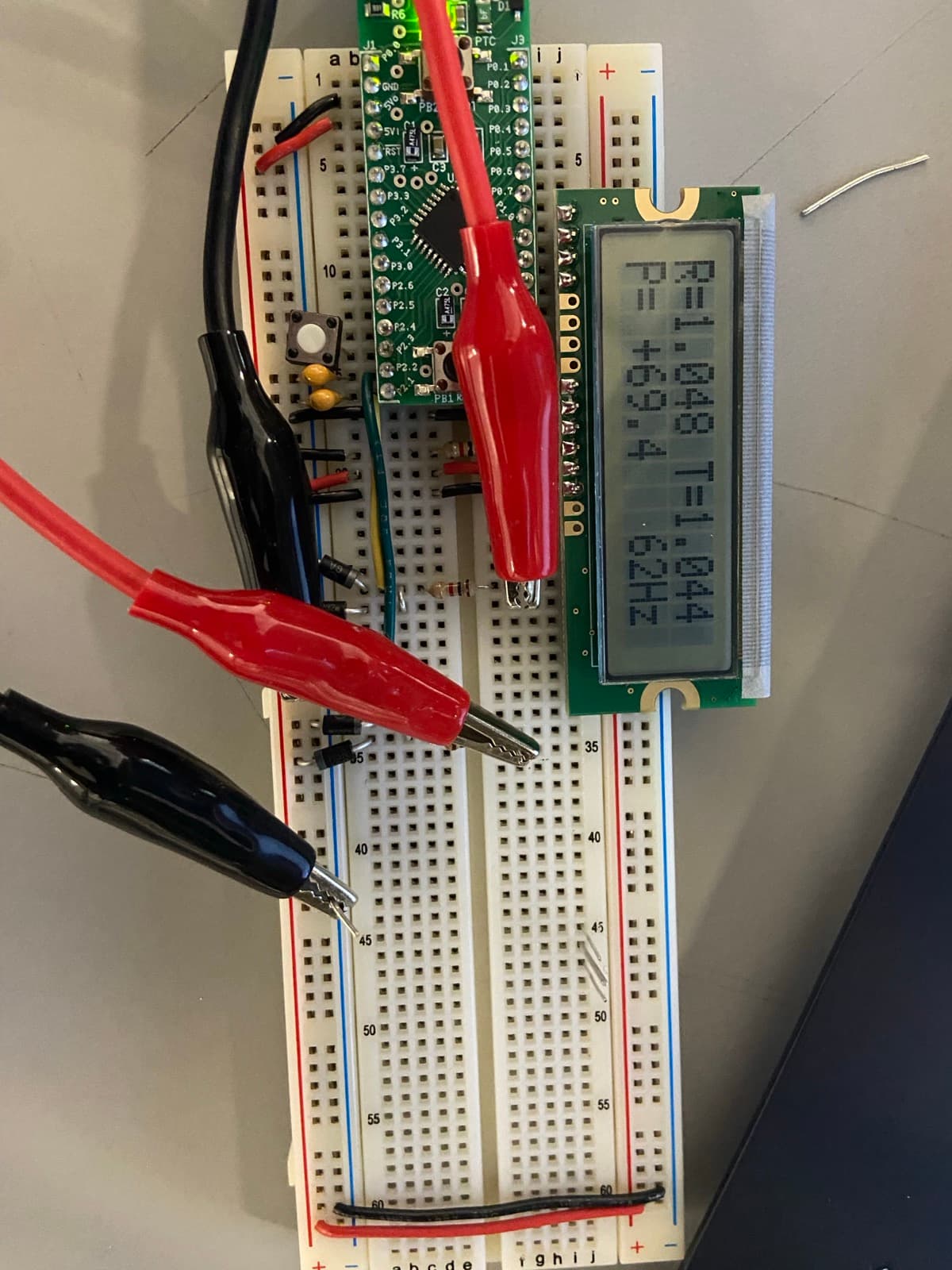
A microcontroller-based AC instrument that reads two analog channels (a reference and a test signal) and displays RMS magnitude, period, phase difference, frequency, and power factor in real time. Built on the EFM8LB12F64 in C using the on-chip 14-bit ADC; all signal processing happens on the MCU.
A single hardware timer does both the period measurement and a quarter-period delay, so the ADC samples the peak of the sine wave at the right moment. Peak ÷ √2 then gives RMS without an analog detector. A button on P2.3 cycles between four LCD display modes.
Specs
- Microcontroller
- EFM8LB12F64 (EFM8 Laser Bee, 8051 family)
- System clock
- 72 MHz internal oscillator
- ADC
- 14-bit on-chip SAR @ 18 MHz SAR clock, ratiometric to VDD = 3.3 V
- Inputs
- Reference on P2.2, test on P2.1 (both AC sinusoids)
- Period measurement
- Timer 0 in 16-bit mode @ SYSCLK / 12 (6 MHz tick)
- RMS
- Peak ADC sample at quarter-period offset, divided by √2
- Phase
- Time delta between ref and test rising zero-crossings, scaled to degrees
- LCD modes
- RMS+phase / leads-lags / power factor + period / peak + ω
Signal pipeline
The main loop runs as a four-stage cycle. Stage 1 measures the reference's half-period: clear Timer 0, wait for a zero-crossing-up on P2.2, start the timer, wait for the next zero-crossing-up, stop. The captured count divided by SYSCLK / 12 gives the half-period in seconds, and frequency falls out of that. Half-periods below 30 000 ticks are rejected as noise.
Stage 2 samples the peak of each channel. With the half-period known, Timer 0 is preloaded to overflow exactly a quarter-period after a fresh zero-crossing-up, where the sine wave peaks. The ADC reading at that instant is the peak amplitude, and dividing by √2 gives RMS. That avoids an analog peak detector or a full Riemann sum in software.
Stage 3 measures phase. Both timers are reset at the reference rising zero-crossing, then we wait for the test signal's rising zero-crossing and read the elapsed time. (time_diff / half_period) × 180° gives the phase angle, with a small correction term for the offset introduced when the two channels have different amplitudes. The threshold-crossing happens at slightly different fractions of each waveform if the peaks differ.
Stage 4 derives everything else: power factor as cos(phase_rad), period in ms as 1000 / freq, angular frequency ω = 2π·freq. Four LCD modes (cycled by the P2.3 button) expose different combinations of these.
q_preload = (unsigned int)(65536.0 - half_period / 2.0);

while (ADC_at_Pin(QFP32_MUX_P2_2) > ZERO_LOW);
while (ADC_at_Pin(QFP32_MUX_P2_2) < ZERO_HIGH);

TH0 = (unsigned char)(q_preload >> 8);
TL0 = (unsigned char)(q_preload & 0xFF);
TF0 = 0; TR0 = 1;
while (!TF0);            // wait quarter period to hit peak
TR0 = 0; TF0 = 0;

peak_ref = ADC_at_Pin(QFP32_MUX_P2_2);